|
Centerboards are very interesting when considering performance improvements to a Dolphin. Some people think that, assuming decent sails and bottom condition, your centerboard is the most important performance variable. Its shape, location and depth affect speed/drag, weather helm and pointing. I have had, for some weeks, discussions with marine architect Mark Steinhilber (Rascal) on the Dolphin centerboard, and centerboards generally, which appears lower on this page - it took a while to translate it.
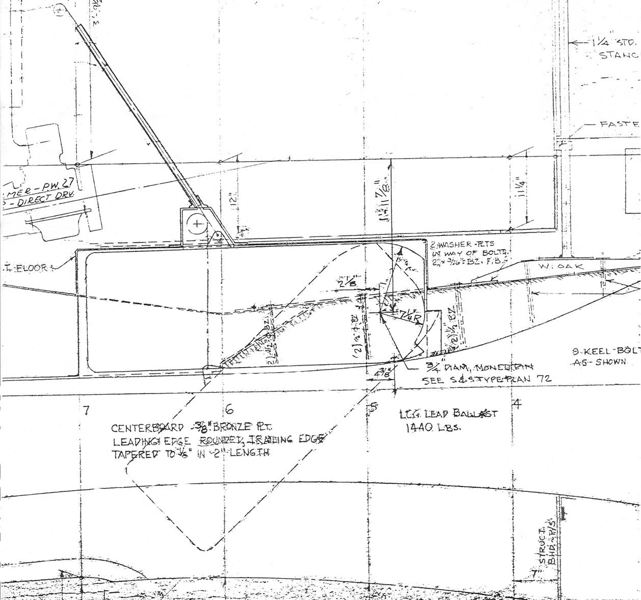
With that gambit in front of us, lets look at the original S&S drawing # 1497, centerboard section, review what has been done or can be done to Dolphin centerboards.

Click here for a larger view To get back here click the back arrow on your browser
This drawing section was recently sent to Ted Prohov (Wada Boat) by S&S. Wada Boat has lost her centerboard due to a suspected broken pin. Ted is undertaking to install a stainless steel board that has been hiding in George Watt's (Odile) basement closet for more than 20 years. That board can be seen on Odile's page. More about this project is expected when Wada Boat is hauled this Fall and a detailed inspection is made. Hopefully, Ted will keep his camera nearby.
Webmaster Note - updated March 26, 2018: Ted's first email about his centerboard set off a flurry of Dolphin network activity producing some updated information about Dolphin centerboards - this resulted in the need to update this page - and check out http://dolphin24.org/wadas_new_CB.html - very important re Yankee CB design changes.
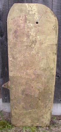
1. Materials - these boards have been made of aluminum, galvanized steel, stainless steel, steel/fiberglass wrapped, fiberglass with lead shot, and both bronze plate and cast bronze - with weight varying from 52 # to 120 #. Both Marionette's and Passage's boards are bronze cut from 3/8 inch flat plate. The heavier bronze was the material of choice but was expensive. Lack of foil shape is a problem with flat plate. The best you can do is grind a bullnose on the leading edge and feather/taper the trailing edge to a small, sharp edge flat.
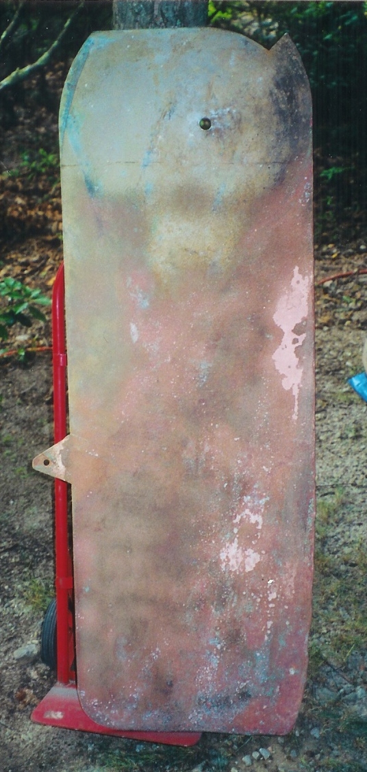
This is a picture of Passage's centerboard before we did anything to it. After early grinding but before some final grinding and painting this board weighs 95 lbs. I'll bet the original, as-new, board was 10lbs heavier. Just as a matter of interest the weight of the rudder and rudder stock was 30 lbs.
According to the November 8, 1968 S&S memo from John Meade to Rod Stephens "Improving the Performance of the Dolphin" Harold White built a 120# cast bronze board for his Imp (now Jay Picotte's Recovery) with an elliptical foil shape, a blunt leading edge and a sharp trailing edge.He built the molds himself using plywood because the plies provided a visual check on the airfoil shape. The maximum chord shape was placed at 37.5% of the board width back from the leading edge.
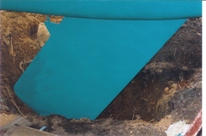 |
2. Depth and angle - the original set up has the centerboard's full down position at a back sloping angle of about 50 degrees. This picture is of Marionette's board in the full down position in the 'hole" we dug to fully access the board. (Webmaster Note: At this point it would be nice to have a power lift with slings in the barn or, even better, a small travel lift, but there are limits... So, how do we get the boat off the trailer and on to poppets without a lift? click here)
The draft, board down, is 5'2". The angle and depth is controlled by a protruding section of the board on its upper leading edge up inside the keel section that you can't see. This protrusion comes up against an internal stop. If you cut off the protrusion the board can rotate past the stop and go to a straight down position against the inside front edge of the keel slot - gaining around 8 " in depth, more weight lower down, more wetted surface exposed and more area forward. These add considerably to the mix of performance variables available from your board.
|

|
This is a picture of Passage's centerboard 'protrusion" stop. We cut it off so the board will go further forward, and deeper |
|
On the left is a photo of the full board before final sanding/grinding and paint. Below is the original board with the stop placed where it was before we cut it off.
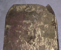 3. Finish - With these old bronze boards, pit and scale can be a problem and it's hard to get and maintain a really smooth finish. They rattle around in the barnacle encrusted lead keel slot and slide up and down against what can be a rough keel slot edge. I have a stiff batten with sandpaper stapled to it that I run up and down inside the slot each spring. For Passage we are thinking of an inset teflon strip on the inside edges of the keel slot to help deal with this slop problem. The board at the upper left has been ground using a hand grinder - more needs to be done - slow work. It looks worse than it is. 3. Finish - With these old bronze boards, pit and scale can be a problem and it's hard to get and maintain a really smooth finish. They rattle around in the barnacle encrusted lead keel slot and slide up and down against what can be a rough keel slot edge. I have a stiff batten with sandpaper stapled to it that I run up and down inside the slot each spring. For Passage we are thinking of an inset teflon strip on the inside edges of the keel slot to help deal with this slop problem. The board at the upper left has been ground using a hand grinder - more needs to be done - slow work. It looks worse than it is.
Marionette's board has never been removed (by me) but it sure would make help working on it if I could take it out easily. Getting the pin out was a challenge on Passage. Three guys taking turns with a 10 lb sledge using hardened steel 1/2 inch drive pins. Probably not a good thing for keel bolts. If and when I remove Marionette's board I am thinking of drilling the pin out - maybe with a portable horizontal drill press. Meanwhile we need to figure out a neat way to have an easily removed pin that does not compromise security. Being able completely drop the board out, without a major hassle, to wet sand and paint it would really nice. For more on the very important centerboard pin click here.
|
|
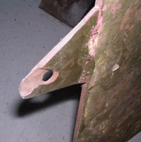
This is the tang of Passage's board to which attaches the shackle for the uphaul wire. Note the corroded, broken away section, surface pits, and the surface pits in the above photo. We have been 'thinking" on this corroded tang issue. The ss shackle/ss wire system is worth consideration - electrolysis issue... We may weld on a new tang, or maybe just beef up the tip?
|
4. The 'climbing centerboard - The keel slot is 3/4 " wide, twice as wide as our 3/8" thick boards. At least one enterprising Dolphin racer endeavored to use this fact to make the board be a kind of climbing board. He added teflon pads to the trailing edge of the board on either side placed so that when the board was fully down the pads were just inside the keel slot. This 'locked' the trailing edge in the center of the slot but the leading edge of the board was free to slide on the pin permitting a small 'cocking' of the board to windward. This man is the same guy who first figured out how to get his board deeper and more forward. A thinker...
5. Slot turbulence - this is bothersome to dinghy sailors. They like stiff mylar strips overlapping the slot that seal the slot when the board is up, and seal up against the board when it is down. This requires routing a thin narrow groove on either side of the slot into which a thin, probably fiberglass batten will fit holding down the mylar. A thing of beauty to behold. Maintenance would be, of course, a significant issue - and it is a stretch to call a Dolphin a dinghy - but then there is that turbulence...
********************
As we know the centerboard has a stop built in to prevent the Dolphin centerboard from going to the fully down, straight vertical position resulting in a 50% angle instead of a 90% angle, and shallower draft. I asked Mark Steinhilber, (Rascal) and a marine architect, why he and his father, among other early Dolphin racers, tinkered with their centerboards in the 1960’s and 1970’s. I asked if he could explain why the design was the way it was, why and when there might be some performance advantage to remove or modifying the stop and to comment on foil shaped boards and 'climbing boards".
Here is Mark's reply (minor edits)
The centerboard angle was designed to put the center of lateral resistance (underwater) approximately right under the center of effort of the sailplan - to balance the helm. With higher winds and a limit on flattening and de-powering the mainsail, the center of effort of the sailplan tends to move aft with wind velocity and gives more weather helm - and drag. Letting the board further down in these conditions will tend to increase weather helm - and increase drag. Letting it down too far will expose more of the centerboard pennant which will oscillate in the flow and cause much more drag than when it is just hidden in the trunk. Not much added lifting area was really being gained, it was more a matter of where it was located - kind of an adjustable keel fore and aft to balance the helm.
For that reason, and to limit how hard the board could swing down and forward, on Rascal we only cut the stop an inch or so deeper rather than cutting it completely off. With it completely gone the fully down board may actually have a negative sweep angle - which could become an even better kelp catcher!
So in stronger winds when mainsail shape and trim are adjusted/flattened all the way and can no longer reduce weather helm, actually bringing the board back up a little may be advantageous to balance the helm and reduce the drag from the overly compensating rudder.
In light to moderate conditions, putting the board further down (stop position modified or the stop removed) will make the board a higher aspect lifting surface - yet, with a shorter chord length (length the water actually sees the foil). If the board were shaped into more of a lifting foil shape, instead of just a flat plate being deeper or more vertical, it theoretically will deliver more lift with little increase in drag, i.e., be more efficient, and should make the boat able to point higher (actually sideslip less) because the board can generate more lift. Using the ability to let the board down deeper moves the center of lift forward as the board pivots down, so the effect on the amount of weather helm must always be considered.
As for the tacking aspect of the board (the climbing centerboard) with the trailing edge centering blocks, 2 or 3 degrees of angle of attack may help windward performance, but on other points of sail, it may be unpredictable and cause undesired drag as it steers the boat off centerline. I don't remember how much angle we thought we could get, but I think we thought we were getting maybe 3/8 or 1/2 inch of athwartships movement on the pin. Don't worry about strength, the pin and the bearing faces in the trunk are fine.
To sum it all up, removing the centerboard pivot stop may gain a little performance by getting a little more lift from the board that can benefit under conditions where there is not much weather helm that must be corrected by the rudder (drag). With more lift being created by the keel and board, one can sail higher without pointing or trimming any tighter, it is actually the boat side slipping less, just like heeling over too far causes the boat to sideslip more. More board down may not be always better, especially when it is starting to increase the amount of helm needed. It is a trade-off.
Improving the foil lifting shape of the board through shaping and adding trailing edge centering stops to make the board "tack" a few degrees at most will likely have more effect on generating lift whereas board up and down position may be more useful in reducing weather helm related rudder drag.
What we are talking about here may earn a few seconds per mile in boat speed - often the difference between say a fifth and second place. I'd have to say that shaping the board into a foil will probably have the most noticeable benefit of all. Actually adding thickness when shaping into a foil may have less straight line drag than the flat plate board, yet give it some angle of attack and it will outperform the flat plate in generating lift.
Mark
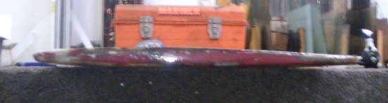
June 23, 2011. Jonnie Walker has been rebuilding the centerboard on his Yankee #227 (click here to go there). Included in that update is some centerboard measurement data that it seems useful to have here as well. This is an airfoil shaped centerboard which is the reason for its complicated construction, and the reason why #227 will point so high. Here is a picture of the board laying on its side. Jonnie's pictures and comments are below.
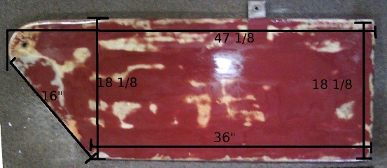
The board is thickest, 1 1/16", at the bottom of the board (the side protruding when down). The thickest part is about 8 inches from the leading edge....the board is 18" wide so it is just forward of center....the bulk of the thickness is forward, with the taper to the trailing edge being more gradual than the taper to the leading edge.
In other words it gets thick fast, and then tapers off.....wing shaped. The trailing edge is about 5/16", the leading edge is about 5/16th
We have come up with the following description of the board's rather complicated construction.
A composite fiberglass board built over wood ribs with internal lead ribs and chunks, sand, and mystery goo filler bonded with resin. The sand voids have been cleared and the lead shot has been epoxied in place to add some weight (10 lbs). The mystery goo filler has been cleared and the voids filled with thickened epoxy. The pennant attachment is a flat L shaped stainless steel piece fitted into the previously sand filled void and glassed in permanently.
Here are some measurements which may prove helpful to those contemplating a repair of a similar construction centerboard.
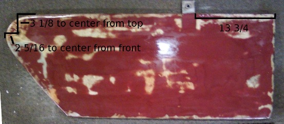
The following picture shows the location on the pin and the attachment plate.
|
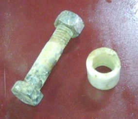
This is what I pulled out of the pivot hole.....I believe it is a hdpe type material. (think white cutting board)
O.D. is 7/8 - I.D. is 9/16. The bolt was 1/2"
I have been debating what to replace the sleeve with....a stainless tube was my first thought, but the more I've thought about hdpe the more I think I may fab a replacement out of it.....it will wear....but no corosion...and its pretty slick...so it should move very well....and that one has been in there for years and worn only 1/16". The wall is 3/16".....so I think it would last 10-20 years.....maybe.... Any thoughts? The Webmaster agrees with Jonnie's approach
-jonnie
|
For informational, and comparison purposes, here are the measurements of Passage's centerboard
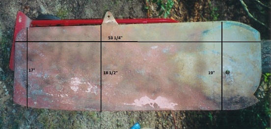
Overall length, 53 1/4"
Width 17" at 2" from the bottom edge
Width 18 1/2" at tang
Width 19" at top just below pivot hole
Thickness 5/16"?, 3/8" when painted, flat plate, blunt rounded at leading edge, smaller rounded at trailing edge
***********************
October 23, 2011. Here is an interesting link to a technical summary of centerboard (and rudder) design http://www.boat-links.com/foils.html. While fairly technical, when read in conjunction with Mark Steinhilber's practical commentary on the Dolphin 24 centerboard (above), these give a pretty good information basis for 'decision making'.
.
|


