|
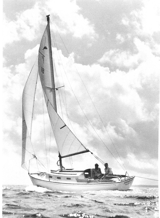
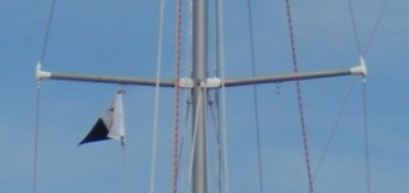
October 15, 2008. Dolphins have that perky upward tilt to their spreaders - this photo by Peter Barlow of # 18 Spindrift that appeared in Frank Kinney's classic book Best of The Best is a perfect example.
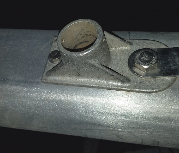
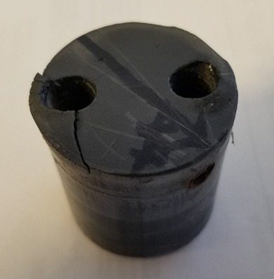
That tilt comes from the shape of the spreader block that is between the spreader bracket and the mast. A failure in the spreader/bracket/block/fastening system can result in the loss of the mast. Here we are talking about just the block. This apparently simple part is, in fact, a very complicated little part. Here is a close up of #10, Passage's.
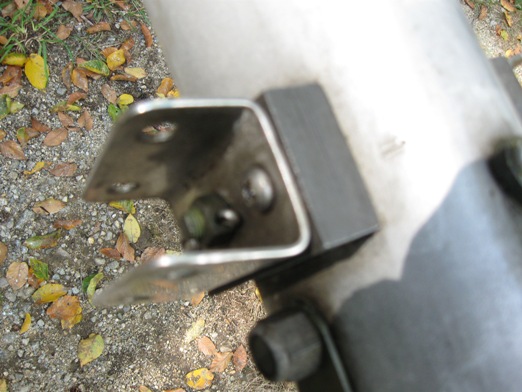
That block has a curved surface to mate with the mast. Note that the lower shroud tang stops below the block. Here's another view.
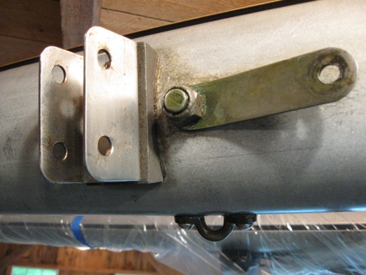
Now here is Marionette's sorry looking bracket and block
I could have cleaned this up more but it would still look pretty bad. Notice the little pieces of stiff plastic stuck under the block at the lower left and center - to take up a small gap between it and the mast. Another point - compare Passage's bracket location relative to the lower shroud tang and Marionette's. Passage has two through bolts in the mast, one for the shroud tangs and one for the spreader brackets - Marionette's only one does both jobs. Here's another view:
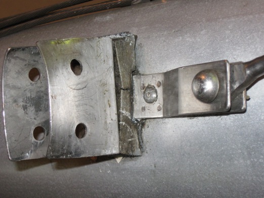
You won't fail to note the cracked block. This set up on Marionette might save a bit of weight aloft and cost a little less but it also means that, because of the tang beneath it, the support block under the spreader bracket is more complicated, and vulnerable to problems as you can see. This block appeared to be a cast aluminum block that was machined. The tang, at first glance, looks pretty solidly fastened to the mast - 3 rivets and the through bolt. A closer look at the picture below reveals that the tang has 2 pieces, presumably spot welded and fastened with one rivet. One leg of the tang stops and the other carries on under the spreader block and to the 2 rivets above. I have no idea what shape the weld is in.
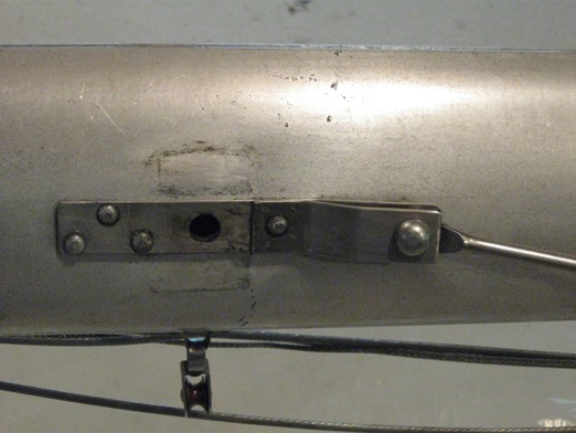
That's not a dent or deformation, although it does look like it. Maybe more worrisome is those black specs that are probably corrosion. Ok, back to spreader blocks. Here is the assembly from the back side.
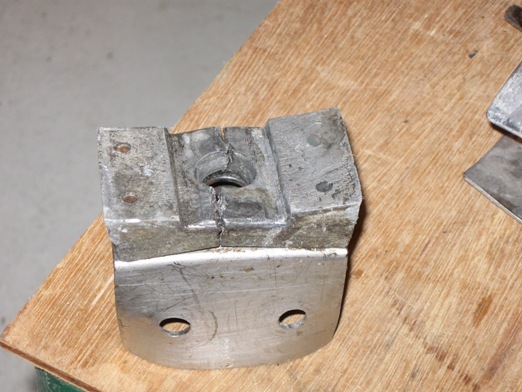
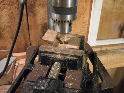
So, here we are. The assignment is to make 2 spreader blocks to replace these sorry looking blocks - yes, both blocks were cracked - without requiring a home equity loan. Making this more complicated was the fact that Marionette's mast is 'tear drop' shaped so that the the curves fore and aft are not the same. The decision was to make these blocks from a very high density, hard Brazilian mahogany type wood, whose name I cannot remember, that would be easier to machine than metal, would not compress, would resist weather rotting, and hopefully would not crack. I cut a 12-14" long blank the right width and max height on a table saw, then turned the blank on its side, tilted the blade and cut the the taper on the same table saw. Then I cut the long blank into several short blanks the right length. Besides making the taper job easier with a long piece, having a few extra blanks seemed a good idea as this job looked like something I might have to do again.
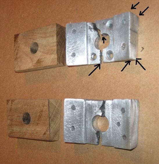
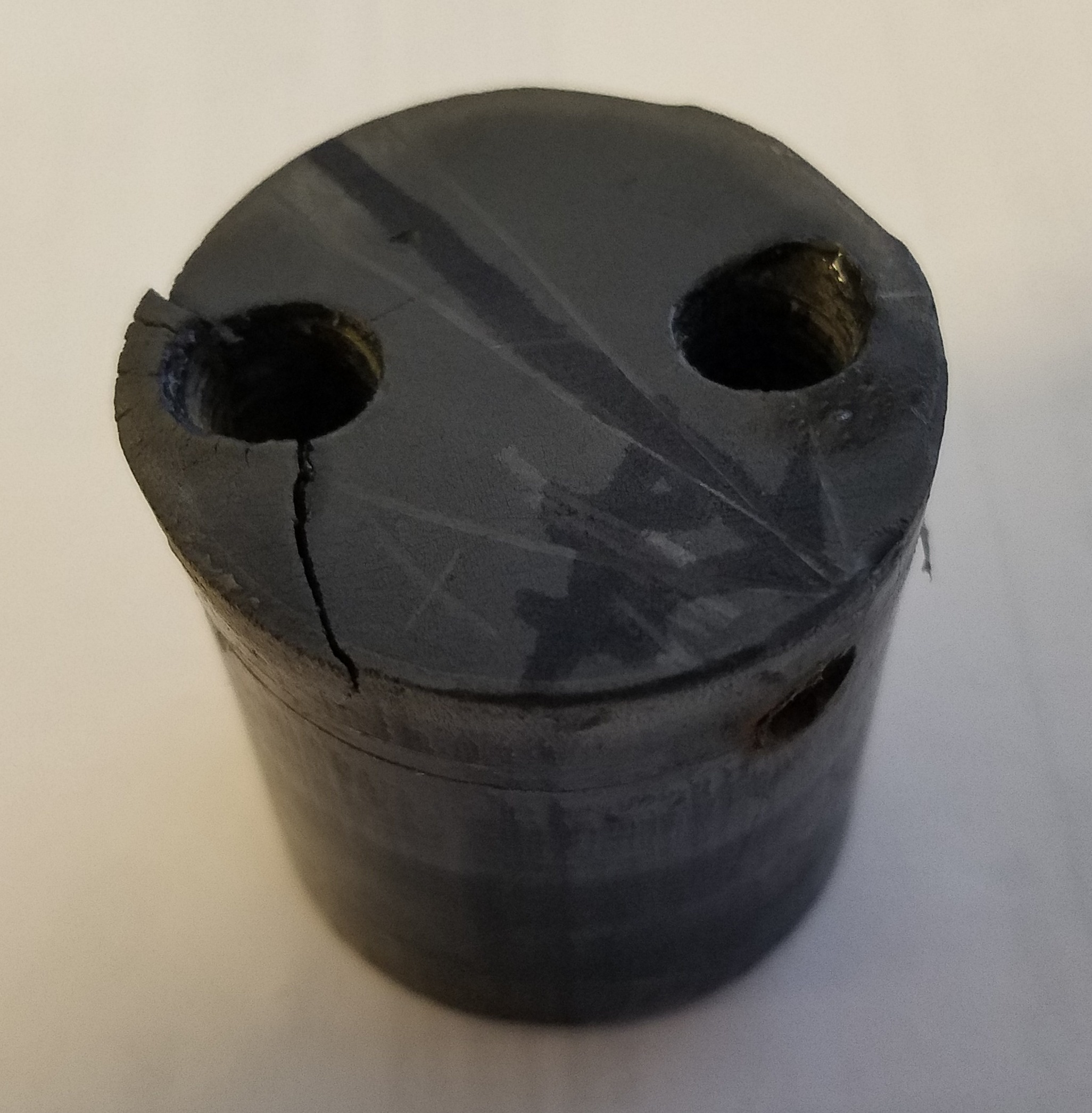
Below is a picture of both the cracked spreader blocks and the two straight tapered blanks I made. The metal blocks cracked vertically so I made the new blocks so the wood grain ran in the other direction. This picture shows the tapers better.
The tricky part now is to rough out the internal tapers from the outside edges to the relief slot for the tang, rough out the relief slot, and then to get the right curve to mate to the mast curve. The 'workshop' on the second floor of the barn does not have a table router so I used a drill press with a router bit. I located the blank in the piece holder so that the angles were about right and, in progressive steps, 'nibbled' the excess material by sliding the piece holder on the drill press tool/fixture holder base - which is adjustable for height .Worked pretty good.
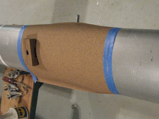
The tang slot was finished using a fine wood rasp and then wrapping the flat rasp with sandpaper. The final curves on the mast mating side were hand sanded using the mast itself as a guide. The sandpaper was taped to the mast and each of the blocks sanded in the same location and orientation as they would be eventually located on their own side of the mast.
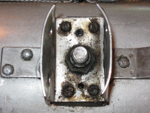
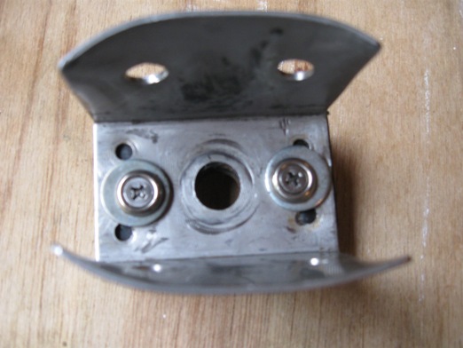
Here is a side view picture of the new block assembled to the bracket. Note, barely visible, that there is a piece of thin rubber compressed between the 2 parts. That bracket had been subject to a lot of holes, stress, etc, as you will see in the following picture. I thought that this would be a good idea - yes?

Below is the view looking at the attachment end of the bracket, with all its extra holes in the base. The washers are eccentric to the outside edge so I could tighten the hex bolt head and hex lock nut. You can see that the bracket base has been 'worked'. Passage's bracket is made of a thicker gauge and looks practically new...
One might wonder why I did not fix this cracked base problem when I first noticed it years ago. At that time I was just putting the mast up in the Spring so, as a short term fix, I decided to use a ss hose clamp around the base to help hold everything together and hopefully prevent another crack or a fastener failure. It worked, there was no sign that it would not continue to work, and the years went by... But, I decided to make this off season the "go over the mast season" and fixing this was high on the list. The hose clamp idea seems such a good one, I had them already formed, and since the wood base idea was not proven, I decided to stay with the hose clamp system as a back up. Here is a picture.
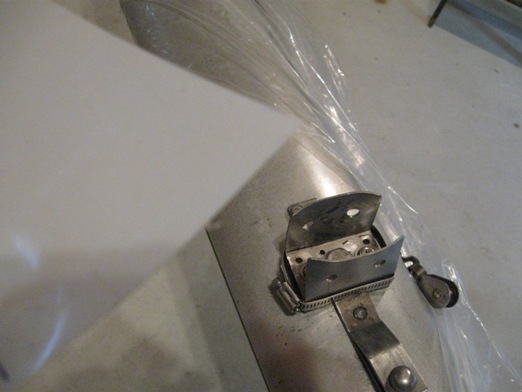
So, what's with that piece of thin stiff Mylar in this picture? Despite all the 'planning and precision machining and hand sanding to fit' I still had a couple of small gaps between the block and mast that a couple of slivers of this mylar filled nicely. In the Spring when I tape this all up with white plastic tape to avoid halyard and spinnaker snags they will be taped in place and no one will see.
 I don't know how old Marionette's mast is - it might even be the original. Another project this Fall, not yet finished, is to replace the old aluminum gooseneck slide track for the boom (that scary looking thing on the left) with a bronze track. I have already beefed up the gooseneck slide. (click here to go to the gooseneck/slide track project) The standing rigging and related fittings seem in excellent condition, due, no doubt, that they are always soaked in WD 40 all winter. Still, living with a couple of hose clamps around around one's spreader blocks for a few years, plus close up and personal work on this mast, and constant review of the above photos that don't lie, has me, not surprisingly, thinking about a new mast - lighter, no corrosion worries, better performance, etc. This spreader bracket block project, if successful, will give me the time to study a new mast further, and defer still further that home equity loan. Look for an article on new Dolphin mast options and evaluation in the coming months. I don't know how old Marionette's mast is - it might even be the original. Another project this Fall, not yet finished, is to replace the old aluminum gooseneck slide track for the boom (that scary looking thing on the left) with a bronze track. I have already beefed up the gooseneck slide. (click here to go to the gooseneck/slide track project) The standing rigging and related fittings seem in excellent condition, due, no doubt, that they are always soaked in WD 40 all winter. Still, living with a couple of hose clamps around around one's spreader blocks for a few years, plus close up and personal work on this mast, and constant review of the above photos that don't lie, has me, not surprisingly, thinking about a new mast - lighter, no corrosion worries, better performance, etc. This spreader bracket block project, if successful, will give me the time to study a new mast further, and defer still further that home equity loan. Look for an article on new Dolphin mast options and evaluation in the coming months.
As always, critical comment and input on this subject is requested and welcome.
***********************************
April 27, 2014 Finally got around to updating this 'new mast' reference. Click here to go there.
************************
September 13, 2016 Mike Zint, (Grand Finale, Pacific Dolphin #300) reports on a spreader problem.
Ron,
I almost got the mast raised for the first time yesterday, but the port side spreader wouldn't stay attached to the mast.
Here is a photo and below a blue print I made from the defective part. Luckily I can flip this one and redrill the roll pin hole.
Mike
Click here for a larger image
|
|
Stay Tuned
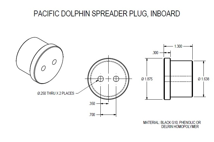
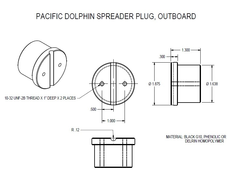
September 29, 2016. Pacific Dolphin Spreaders - Mike continues....
Finally got mine apart. All components measured and documented. Ordering new material to remake the inserts as mine are brittle. Imagine that. LOL

to be continued
*****************************************************
January 17, 2017 - Continued (edited)
Hi Ron,
I got the lathe work done on my new spreader mounts and caps but haven't done the drilling and tapping yet.
One question I have on this.Should the outer cap clamp tight on the shroud or should it allow the shroud to slip through? The old ones look like they were set up for the shroud to slip through as it looks like it's a 1/4" diameter groove for the 3/16" diameter shroud wire to go through. Is this design or wear?
Mike
Webmaster Replies -
Hi Mike
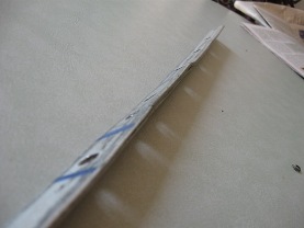
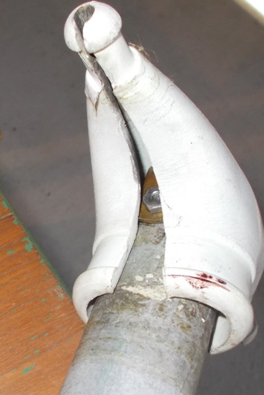
Its the design. On Marionette's spreader tips (below) the handmade "C" clamp' merely holds the shroud in against the groove in the spreader tip.
Very important - after tuning I use my whisker pole to position the spreader tip to get the 'perfect', slight up, angle for the spreader. The spreader boot tips are taped closed but the shroud is 'free' to slide in the groove.
Ron
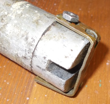
Much prettier when taped....
|
|
**************************
|


