|
Webmaster Note: To get a more indepth view of the subject be sure to read over the other articles in the Technical/ Rudders and related Section
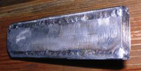
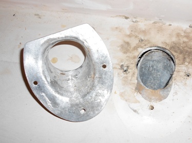
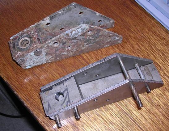
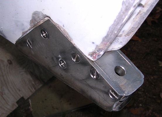
Passage had a fabricated stainless steel rudder post heel fitting that had a lot of pits and corrosion, and the bottom plate was completely missing. The following picture has the old and new fitting side by side. In the final assembly, the bottom plate is welded to the cheek plates. The rudder post has a stub which fits the guide plate hole - the surfaces are separated by a heavy duty plastic washer. The rudder post stub has a cross hole in which a heavy cotter pin will fit. This holds the rudder post in the fitting
|
The bottom plate is a heavy skid plate that protects the bottom of the rudder post if the keel grounds. All parts were made of 304 stainless alloy. |
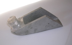
The parts were made with excess material so that the assembled and installed fitting could be ground with a hand grinder to fair the fitting to the keel shape. The machine screws are flat head 1/4 -28 and are counter sunk into one cheek plate and threaded into the opposite side cheek plate - making for two flat surfaces. The old fitting had countersunk screw heads but had plain nuts on the other side. The resulting bumps cost .016733 knots in boat speed, and besides, were ugly.
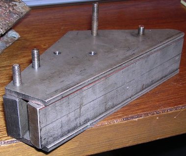
The following picture shows the radiused corners. The fitting will be bedded and gaps will be filled with thickened epoxy and faired. A purist will no doubt note the failure to use the same type screw heads...
After some serious thought I've decided this is actually a test to see which type screw head better holds fairing putty, resulting in some future year, another technical article. Stay tuned.
*************************
************************
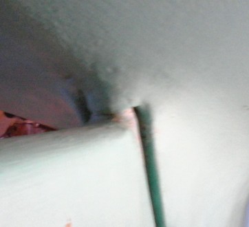
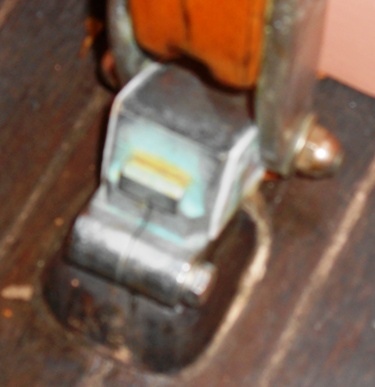
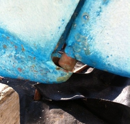
January 9, 2012. Mike Parades (Cove Dweller, Yankee #111) sent in the following interesting photo and email. We are looking into this. Stay tuned.
Hi Ron,
Here is the photo. I don't know the situation at the rudder head. Everything seemed to be moving fine when we sailed her to our wintering site. She was hauled out and put on a hard stand, where I discovered the rudder issue after cleaning her.
Thanks,
Mike
My reply to Mike:
|
Hi Mike
Although I don't have a picture of #111's cockpit I am assuming that the rudder head/tiller connection is on the sole at rear of the cockpit. Marionette's set up is the same. My rudder post can't go higher in the shaft tube as there is a shoulder molded on the post - see photo. If you have the same system then it might have been 'crushed' by some upward force on the bottom of the rudder? maybe a grounding in which case you might see some evidence on the bottom and/or bottom edge of the rudder? Or, perhaps a lifting strap from a travel lift when hauling was too far aft and forced the rudder up?
If you felt no difference on the tiller, and see no grounding evidence, then the travel lift might be a likely suspect. Also, when the boat was moved it might have been lowered, normally on a keel block, then poppits are placed. If there was a block under the rudder that could have caused the upset.
Assuming that the rudder shaft is not bent you might be able to lift the rudder back in place without removing the heel fitting. This leaves the issue of the 'stop' on the rudder shaft that was supposed to stop upward movement....
Ron
|
Mike responds:
The rudder is fixed. For an undetermined reason, the nut at the base of the tiller was very loose. One person pushed the shaft down from above while the second person (me) guided the bottom of the shaft into the slot. The nut was tightened. The tech said everything, including the packing, seems fine.
Mike
*************************
March 1, 2012. While the basic system for fitting a rudder to our Dolphins is the same, there are different details that make repair, restoration, etc., interesting for us. A design difference is that some of our boats have the tiller head located on the cockpit sole, others at the top edge of the transom deck. Generally speaking, boats with motor wells in the transom locker have the tiller head on the cockpit sole giving more room in the motor well. Passage has an inboard - and as she is undergoing a restoration, all the parts are disassembled and easier to see. While some details may be different, the principles are the same, I think.
Lets start with a photo of the complete rudder and shaft on Passage, hull #10.
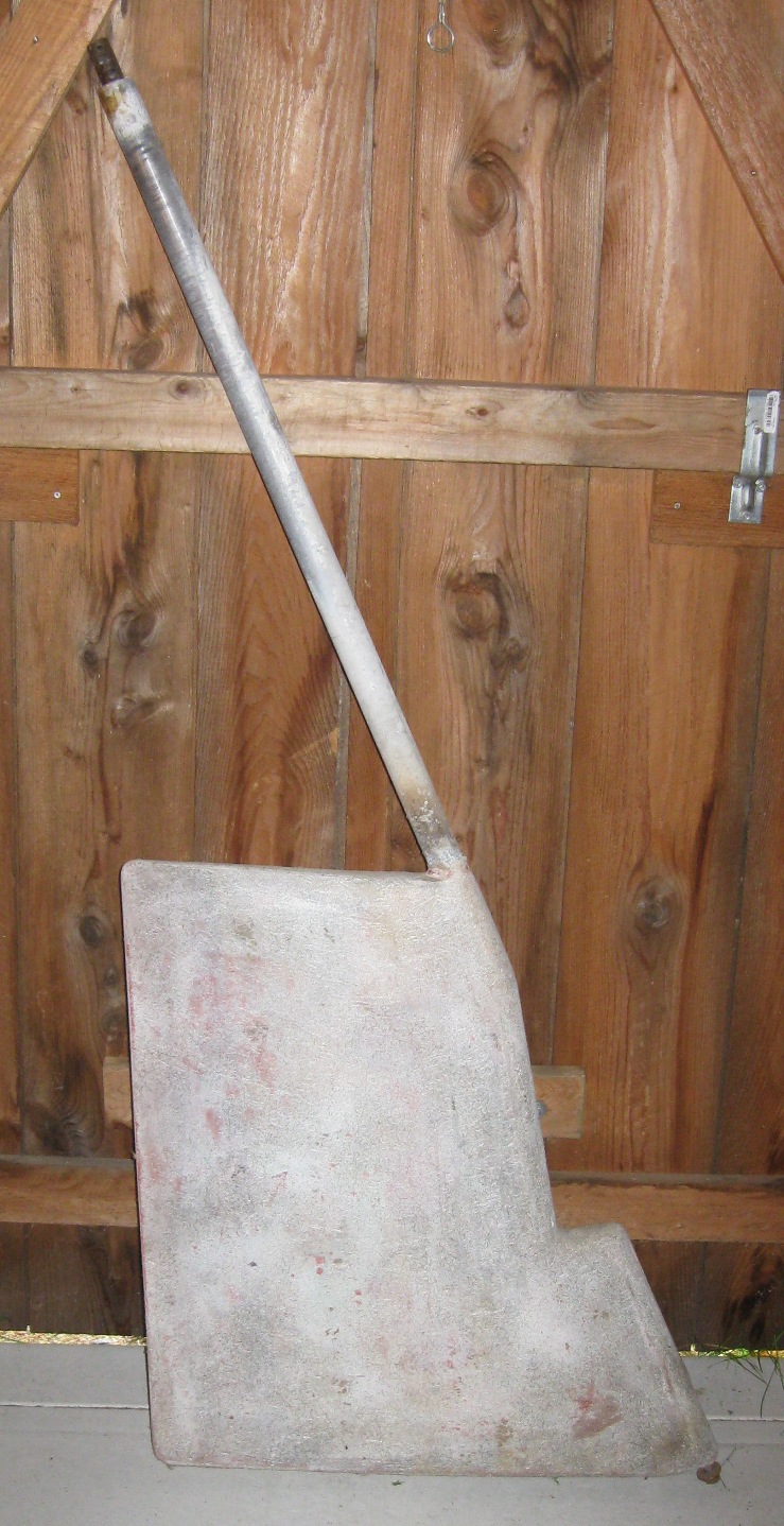
Passage's rudder
|
|
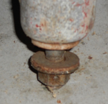
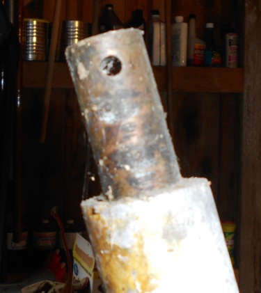
Bottom of Passage's rudder shaft |
Passage's rudder shaft heel fitting |
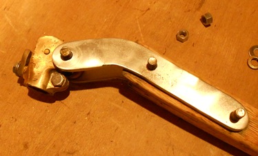
Passage's system has a 'stop' that prevents it from rising up out of the heel fitting - there is a nut at the bottom of the rudder shaft (picture above left). A heavy cotter pin fits thru a hole in the nut and then through a hole in the threaded end of the shaft. Its a bit tricky but you line everything up, screw the nut up to the underside of removable top plate, align it with the hole, insert the pin, and screw the fitting in place. The rudder shaft rides on a plastic bushing between it and the top of the heel fitting. When we get to the rudder fitting out stage of Passage's restoration we will, hopefully, remember to take a picture or two of the final assembly.
|
|
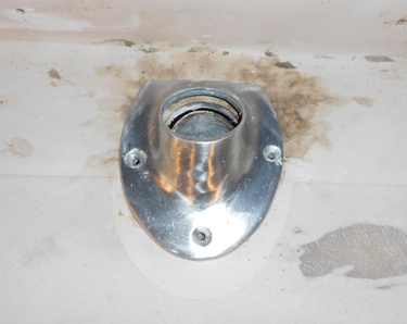
Passage rudder head transom deck plate |
Passage rudder shaft exit hole in deck |
|
|
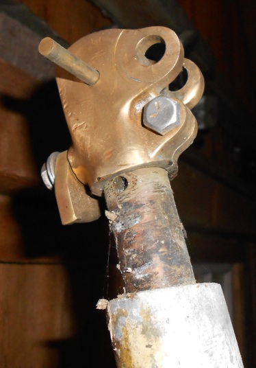
top of Passage's rudder shaft |
Passage's fitting - pin lines up thru hole when pushed down to shaft shoulder |
|
|
Passage's tiller fitting |
Marionette's tiller fitting |
The first 5 pictures in this group show the tiller/rudder head setup on an inboard (Passage) with the top of the rudder shaft located at the transom deck level. In the lower right picture is the set up on a boat with an outboard in a transom well (Marionette) - the top of the rudder shaft is located at the cockpit sole level. The fittings are similar - but neither case is there provia sion for a 'stop' at the top end of the rudder shaft that would prevent the rudder shaft from moving upwards.
I have never had Marionette's out of the boat but visually, it seems that the 'shoulder' on the rudder shaft at the top of the rudder blade would prevent the rudder from popping out should it get upward pressure. Passage's rudder may have the same 'shoulder stop' but I can't tell until it is back on the boat. However, Passage's rudder heel fitting has a 'stop' that prevents the rudder shaft from popping out.
Stay tuned
|