|
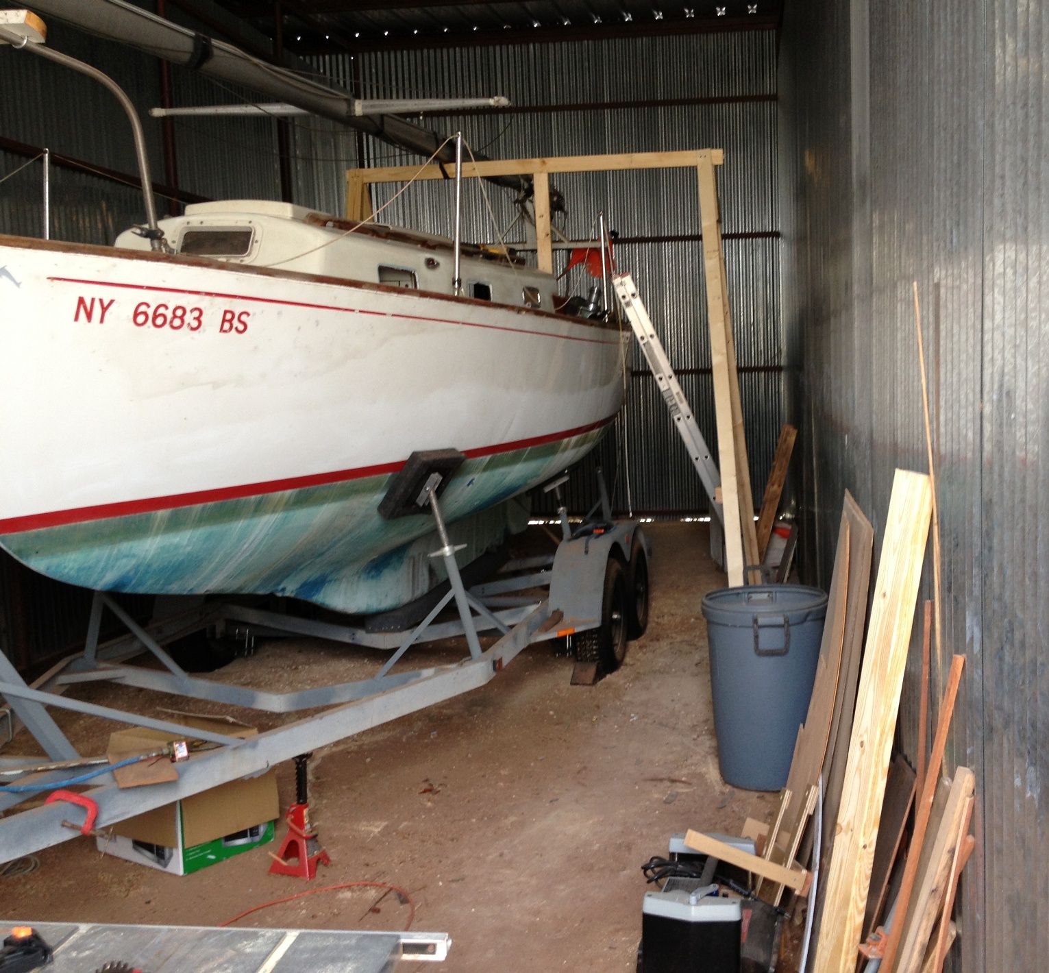
October 11, 2013. Jerry Slaughter, ROWDY, Marscot/O'Day #5 has been working on cleaning up and updating that space between the quarterberths and below the bridge deck and cockpit that Dolphin owners with inboards may lovingly refer to as the "Black Hole of Calcutta". While this project started out on ROWDY's home page it seemed that it should have its own place in our Technical Section.
Here is how it started - where it will end we're not exactly sure. On October 8, 2013 we got the following email from Jerry.
Hi Ron,
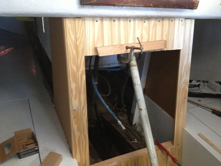
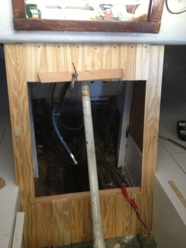
I decided to enclose the engine space with a box with a removable hatch. I will cut the centerboard cable tube and that should allow me to get the engine in and out if necessary. I was going to have a hinged double door for a hatch but couldn't figure a way to make that work around the tube. I would have needed a big slot cut in the doors which would have defeated some of what I was trying to accomplish which was to keep sound and heat out of the cabin. Once I trim out and paint the box it should blend in pretty good. The engine space will be freshened up soon then I will start the detail work to finish things off.
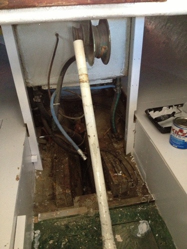
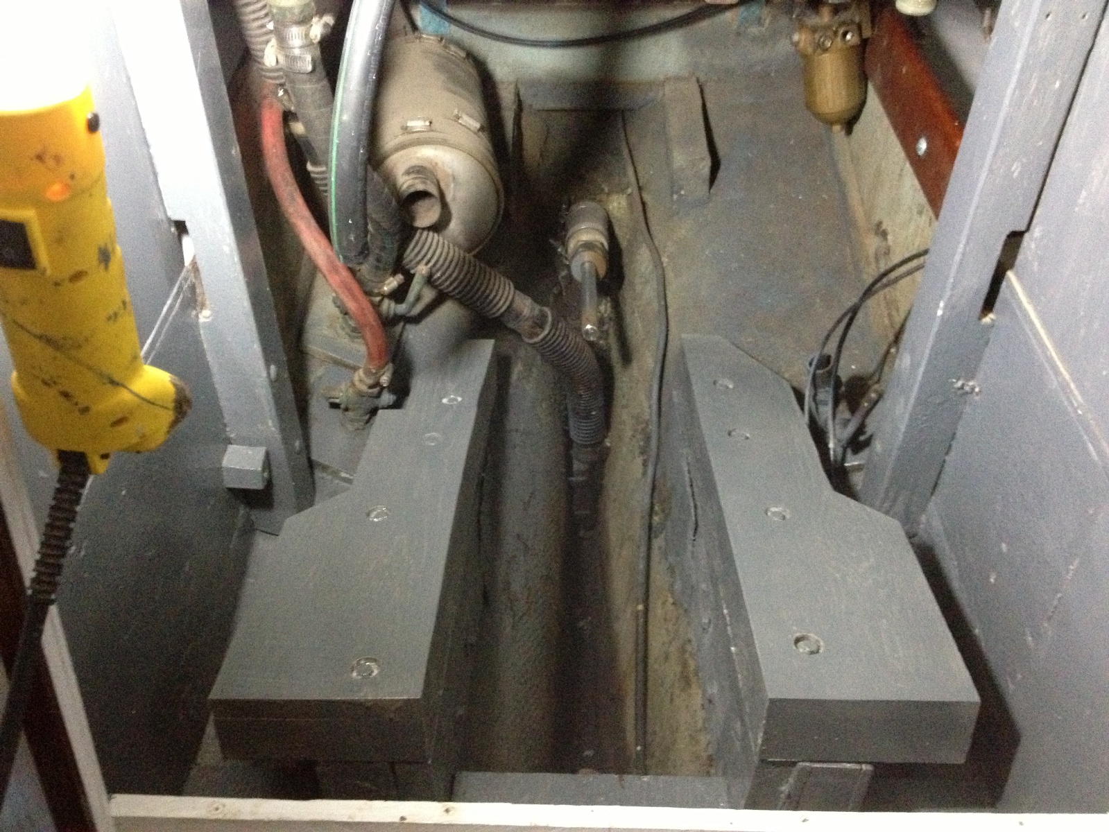
I'm attaching three photos, one showing "the black hole of Calcutta" and two shots of the box, so far
|
|
"black hole of Calcutta" |
Box 1 |
.
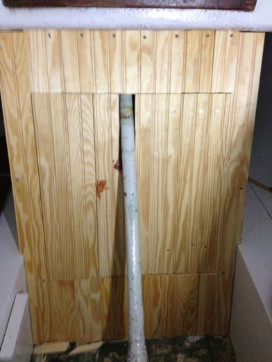
Box 2 - Stay tuned
I pulled the windows last week and was able to save 6 of the trim rings. They are thin aluminum things that I am considering having chrome plated. I wire brushed the rings which made them look decent if you didn't stand too close. For inside trim I will probably use mahogany. I cut some pattern pieces in hardboard and will try to finish the rings with my router and a pattern cutting bit. I'm thinking they should be about 1/2 inch thick so they will not appear to obtrusive in the small cabin. We will see how that goes.
Jerry
******************************
|
October 11, 2013.
Minor edits
Hi Ron,
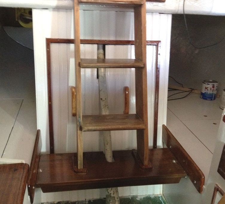
The engine box hatch should be wide enough to allow the engine in. I worked on the hatch a bit today and have about decided to cut the thing in half thereby allowing me to access either the port or starboard side of the centerboard cable tube. Also the hatch is heavy being made up of 3/4 inch boards attached to 3/8 inch mdo. It should be good for sound deadening but not much fun lifting out.
At left is a shot of the hatch rough fitted. Tomorrow will be surgery day and we will see if we like the double door hatch better. If not I'll glue it back together.
Jerry
|
********************************
October 18, 2013. The finished engine box...
Hi Ron,
I finished the engine box (see attachment) and have moved on to stair varnish and window frames. Also I think I may have to make a small modification to the engine box so I can access the centerboard winches. I think that can be done without too much change to the look of the box. As expected, I'll have to paint the cabin sole again. I'll let you know how the windows turn out.
Jerry
**************************
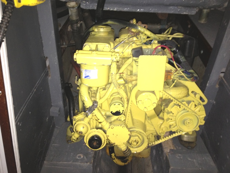
November 27, 2013. Jerry's planning to put in a used Vetus M2.05 diesel in ROWDY. Here are his recent emails on this subject - edited and consolidated.
Ron
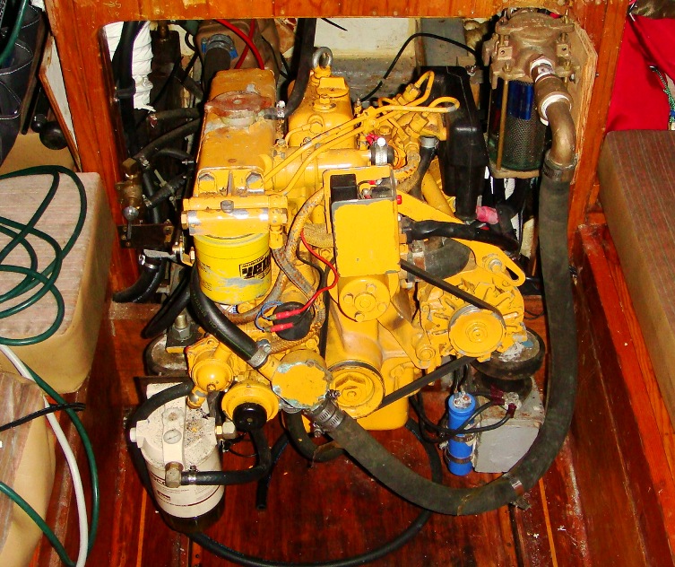
I had a Vetus M2.05 diesel sitting in my garage and thought this would make a dandy engine for Rowdy. When she was new the engine put out about 10.5 hp at 3600 rpm. It's probably closer to 8 hp now although I did a semi-rebuild last year. When I get her spruced up I'll photo her with a yard stick and you will see what I'll be messing with.
When I started messing around in the grey (ex black) hole I found that one of the engine control cables was a Volvo cable and there was a Racor gas/diesel filter attached to a bulkhead. There was also an electric fuel pump attached which would possibly indicate an Atomic 4. Volvo had mechanical pumps, but it is conceivable someone had bypassed the old pump. I haven't put my nose to work yet but a sniff of the filter contents should tell the tale.
It's interesting that your email about the engine should come as I start messing around with my beast. My biggest obstacle right now is making the engine mounts and bell housing work with the current engine bed. I don't think it is going to happen as configured but I'll mock up some templates and see if I can make mods to what's there. Once the engine is in there will be very little room for tools and hands and such.
Happy Thanksgiving to you and your family
Jerry
Webmaster Note: We went on line to look for one of these Vetus M2.05 2 cylinder, 11 HP diesels. Lets hope Jerry has the version that comes with the shoe horn accessory...
************************
December 2, 2013. While most of us have been eating this past weekend, Jerry has been praying....
Hi Ron,
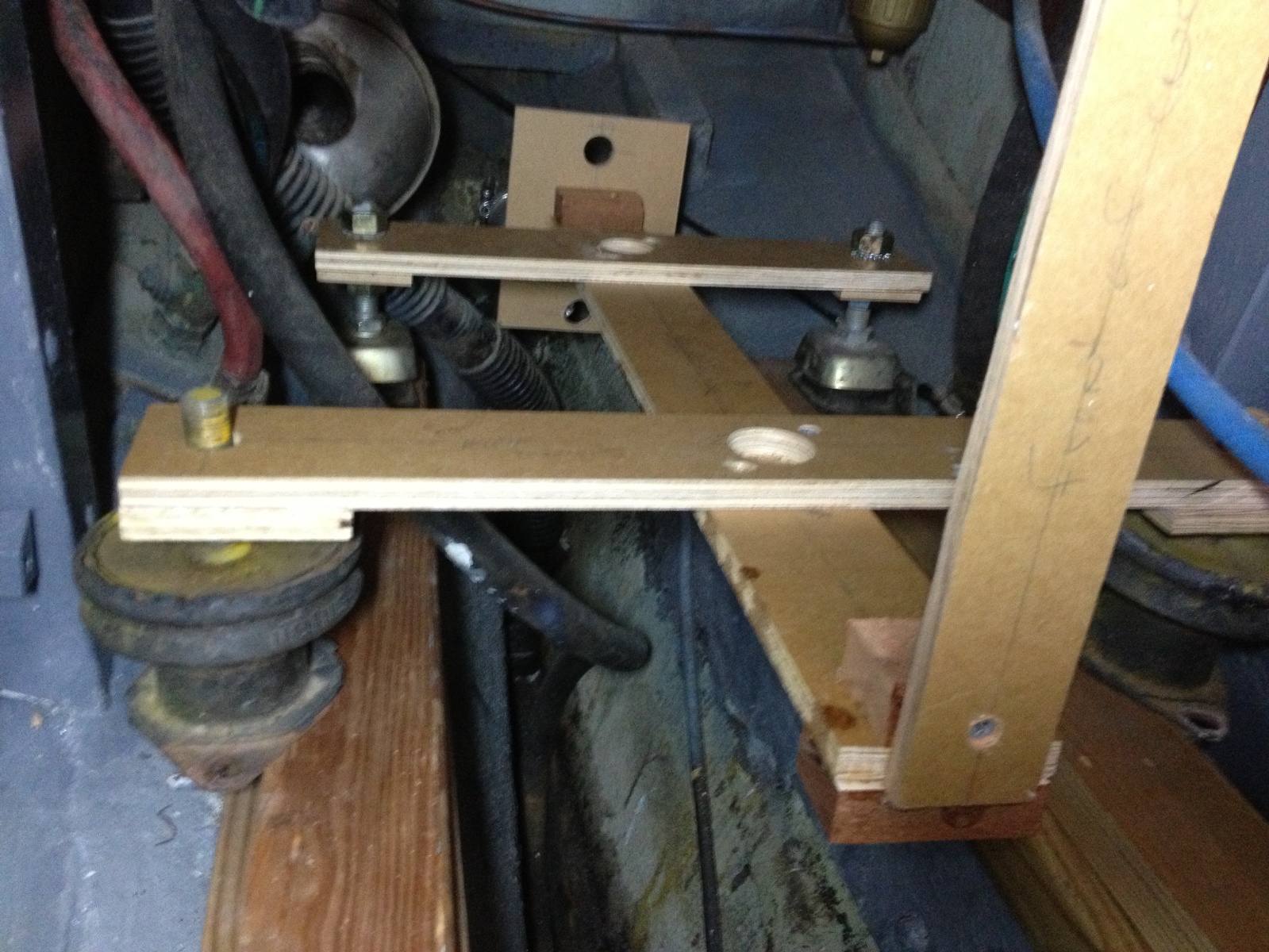
I went out to Rowdy today to make plans for moving this project along. There were a few small things I wanted to get done and I needed to study the engine compartment and beds. I made up a template for the engine mounts and transmission flange to see how the engine would line up using the old bed as is.
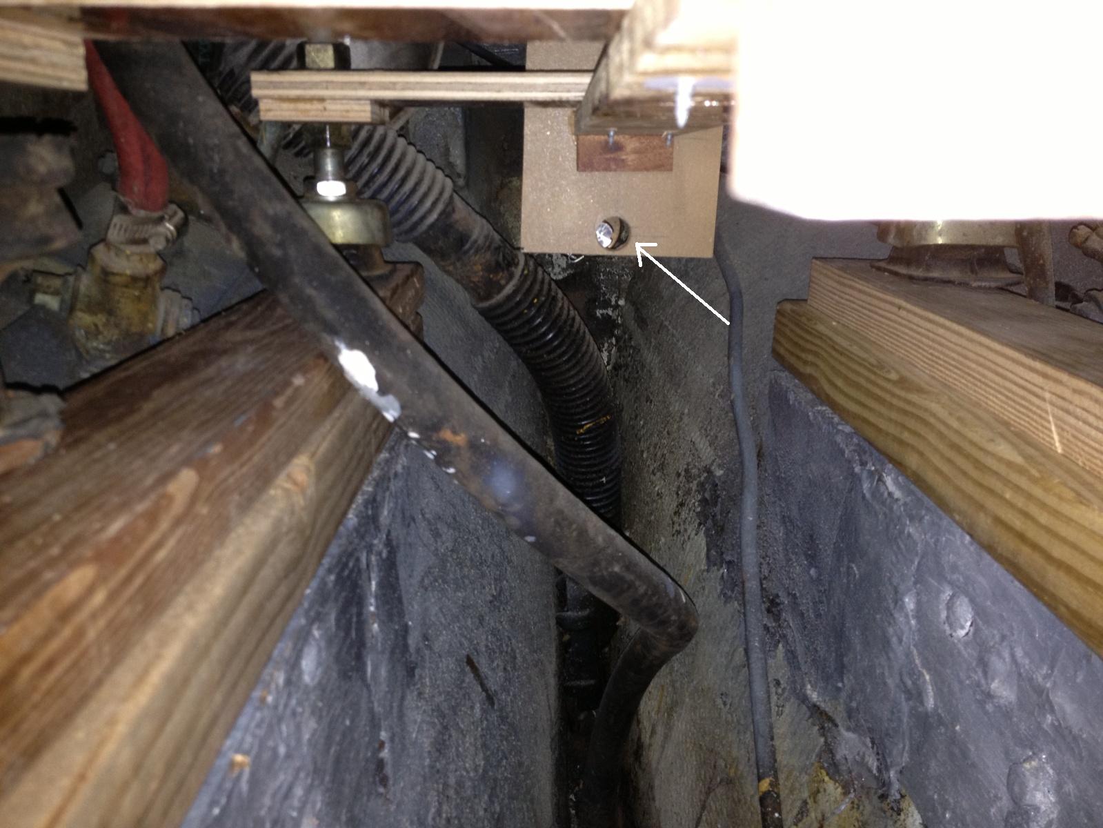
All three pictures are of the template on temporary engine logs. This just gave me the measurements I needed to make the new engine beds. The bottom, underside of the template, shot shows the shaft peeking through the hole which is the center of the transmission flange (see lower right - arrow). That was the key telling me how high I needed to go.
Webmaster Note; Clicking on any of the 3 pictures below will take you to a large view version. Click on it to move around. Click the return arrow on your browser to get back here
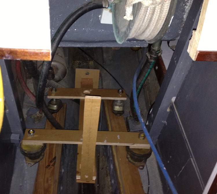
My prayers were not answered. I will have to add 3" of engine bed so the shaft will line up, and the new bed will have to be 6" wider at the front mounts.
|
I was finally able to get a look (sniff) at the fuel filter and in spite of all other indicators the fuel line had gas in it, darn it all. I'll be able to use the tank, after some flushing and I'll have to rig a return line to the tank. I cut out an access panel in the engine box to allow me to get to the centerboard cable and winches. I've got it hinged and I'll put a catch of some sort to keep it closed.
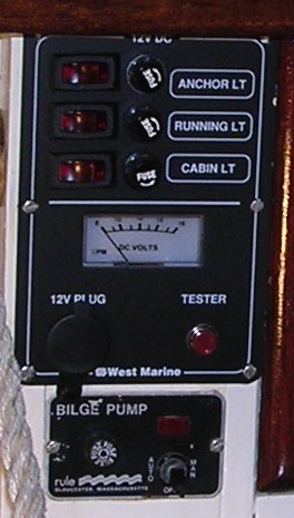
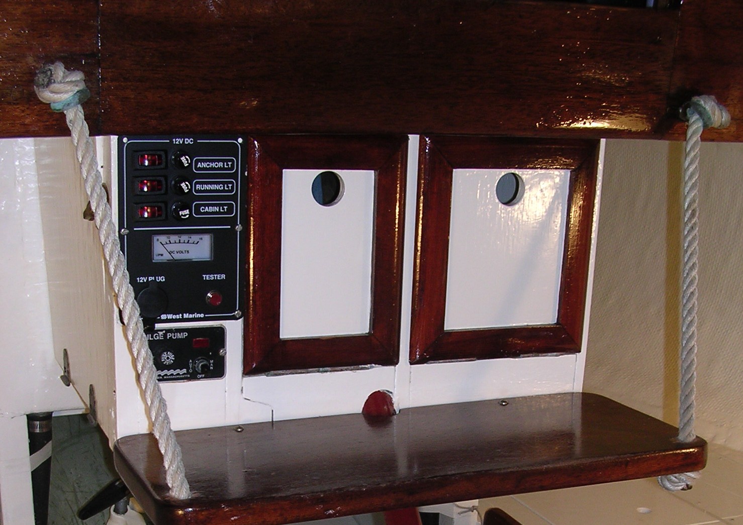
And again, finally, I started running some wire for the running lights and a cabin light or two. I ordered the same electric panel you have and will probably have to add one or two additional fused switches.
Webmaster Note: Picture at left is actually Marionette's switch panel. Click here for a larger view
This boat did not have a steaming light, only the masthead and the port and starboard lights. There also wasn't a stern light fixture but that is an easy fix. I don't recall all the light rules and will have to check.
That's about it for now. Tomorrow I will get some oak and rough cut the engine bed logs.
Jerry
************************
|
December 16, 2016. This is one of those few situations when getting grey is good, and a sign of more good things to come. The following update from Jerry (excerpted)
|
Hi Ron,
Not too much going on worth reporting. I started my Vetus engine and let it run for a bit. For some reason the start button is not working and I'm trying to run down the problem.
I built my electric switch box and put a coat of paint on the frame and cover. This week I will hinge the lid and mount some switches
The engine bed logs Left) are complete and glued and lag screwed to the old bed logs. Primer and paint completed that job. I may yet add two transverse braces but they may not be needed since the original bed logs were glassed in place.
Click on picture for large view
|
*************************************
December 30, 2013. Jerry has to fill this space and it will take some planning and preperation. Here is his latest email (excerpted)
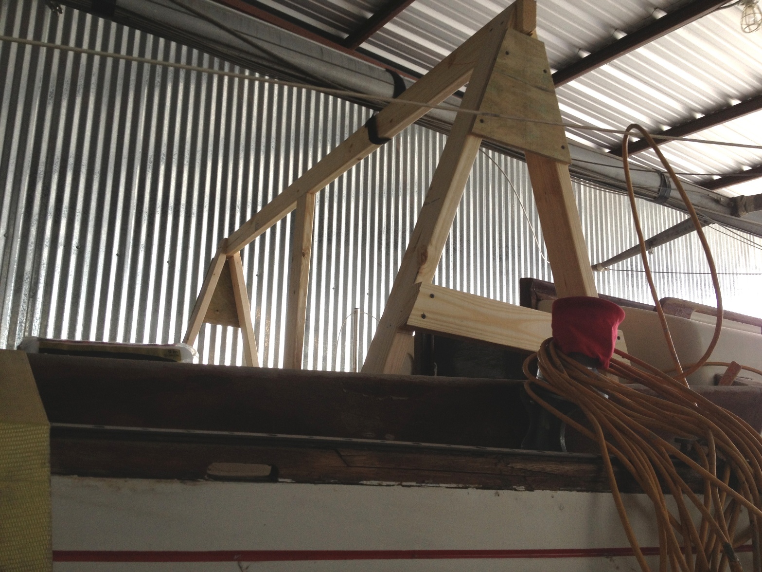
One of the biggies today was building the saw horse for the "big lift". You know I call it a big lift but in reality its only lifting about 250 pounds of inert iron about 8 feet high, moving laterally 3-4 feet and then squeezing through the hatch and onto the engine bed. Nothing to it, in my minds eye. We will see in a day or two. I've attached a couple of photos.
Click on the pictures for larger view, click the new picture to move around; click the return arrow on your browser to get back here
The saw horse has 10 foot legs on one side and 4 foot legs on the other, the deck mounted side. The cross beam is a standard 8' stud supported by plywood gussets. The only add on I will probably use is a piece of pvc along the beam so the hoist can slide easily.
************************
January 6, 2014. The Big Lift. Here's Jerry's report and photos (minor edits)
Hi Ron,
Well the big lift is complete! There were a few bumps in the road but nothing that held up the works for long. I did attach a piece of pvc on the cross beam and that really helped when I slid the hoisted engine inboard. Also I added two lateral brace boards to keep the saw horse from racking. I would have had a disaster without them.
Unexpectedly, I had to make some mods to the engine bed to accommodate the bell housing which caused me to take the engine in and out of its home four !! times. I got pretty good at it, after the first couple of times. It looks like there will be plenty of space in the engine locker but I still have to add a water filter and a fuel filter.
The pictures below show.....
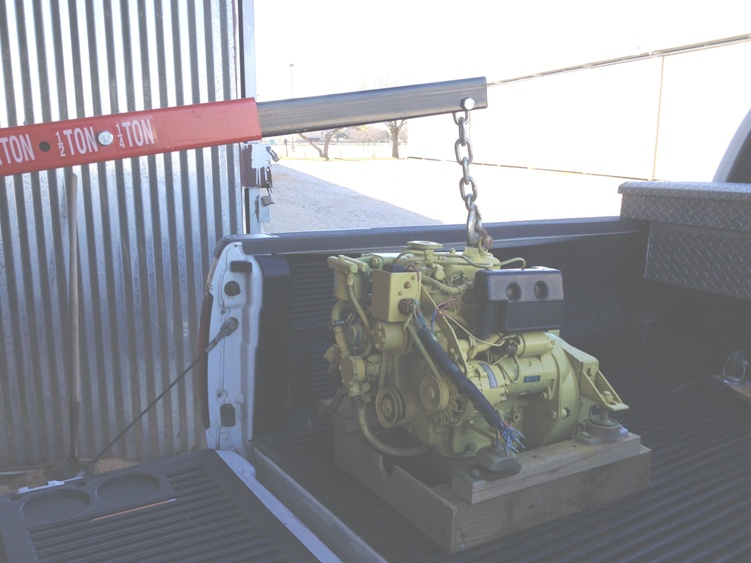
the arrival of the engine at the shop
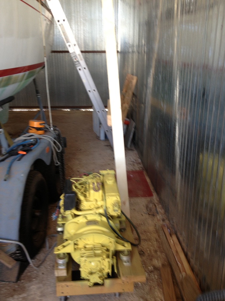
the engine on cart just prior to lift
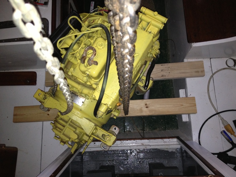
engine just before stuffing it into its home
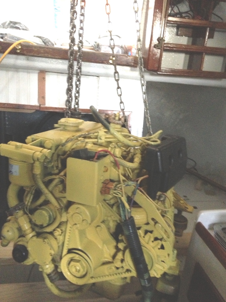
almost in
and, at last, the engine at home. Now I'll drink to that!
I finally got off the dime and completed my lazarette (sp?) hatch. I was going to dry fit it today but got overwhelmed with the engine fitting. I'll take some photos when it gets set up.
Jerry
************************************
January 20, 2013. An update

Click on the picture for a larger view. Click the return arrow on your browser to get back here.
|
I attached the fuel filter and raw water strainer in place and have the water plumbed. The water comes in through the seacock, to the strainer, up to a vent, and then down to the engine. That's almost 9 feet of hose in such a small space.
I'm currently using the fuel hose, from the tank to the filter, that was in the boat. It's a little long but I'll use some exotic routing to take up the slack. I just need a 90 degree hose barb out of the filter to complete the fuel system.
Here's a shot of the strainer and fuel filter. You may notice they are just inside the port side of the engine box hatch, very convenient for servicing, and I still have a little room for servicing the oil filter and coolant.
Jerry
|
*********************************************
|


